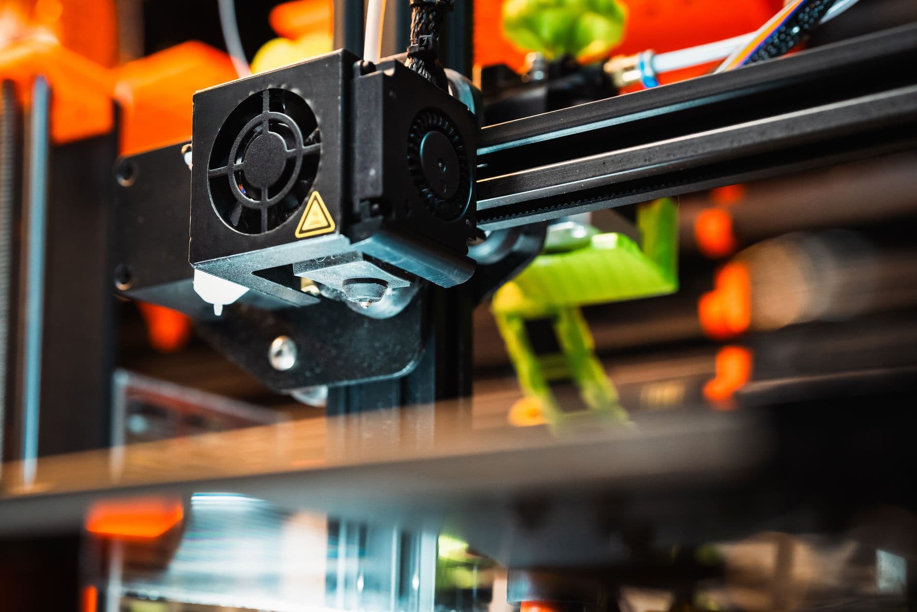
FDM prints hold dimensional accuracy of roughly ±0.5% with a lower limit of ±0.5 mm on standard machines. That means on a 100 mm part you should expect roughly 0.5 mm of variation either side. If your design requires tighter tolerances than that, you'll need to either allow post-print finishing, accept the natural limits of FDM, or consider a different process.
Why FDM can't be as precise as injection moulding
FDM works by melting plastic and extruding it layer by layer. Every layer cools and shrinks slightly, and this thermal contraction compounds across the whole part. The nozzle width, layer height, and material choice all influence final dimensions. Unlike machining or injection moulding, you can't simply dial in a tighter tolerance because the process itself introduces variability at each step. That's not a design flaw, it's the nature of depositing plastic one thin bead at a time.
The material you choose matters too. Different filaments shrink at different rates as they cool. PETG shrinks less than ABS, which is why PETG often delivers better dimensional stability on functional parts that need to hold size.
How part size affects your accuracy
FDM accuracy works on a percentage basis: ±0.5% means the tolerance is a percentage of the part's overall dimension, not a fixed number. A 10 mm feature will deviate roughly ±0.05 mm; a 200 mm part might drift ±1 mm. The catch is the lower limit, which is ±0.5 mm minimum. So if you're printing a tiny part, say 5 mm across, you're still looking at roughly ±0.5 mm of tolerance, not ±0.025 mm.
This is why FDM works best for larger, functional prototypes rather than intricate miniatures with tight dimensional requirements.
Orientation and support placement impact accuracy
How you orient your part on the bed changes how accurately different features print. Features parallel to the build plate generally hold tighter tolerances than those perpendicular to it, because the layer-by-layer nature is less of a factor. Features pointing straight up face more cumulative shrinkage across many layers.
Support material also affects nearby surfaces. Where supports touch the part, you get interference and surface irregularity that can shift dimensions by a tenth of a millimetre or more. Design your supports carefully, or better, orient parts to minimise support contact on critical features.
Achieving better tolerances in practice
If your design calls for tolerances tighter than ±0.5 mm, you have options. The simplest is to print loose and then machine or sand critical features to size. Many engineers design FDM parts with extra material on critical surfaces, then finish them to the required dimension. This turns FDM into a near-net-shape process rather than a final-dimension one.
You can also improve consistency by ensuring your filament is stored dry. Moisture absorbed into plastic increases dimensional drift during printing. A dry box and desiccant packets cost little but meaningfully reduce variation.
Choose your material for the job. Industrial FDM machines can achieve ±0.3% accuracy, but on standard FDM you're working with ±0.5%. If your part genuinely needs better, consider SLA or other resin processes, which hold ±0.3% tolerances and give smoother surface finishes.
When dimensional accuracy actually matters
Most functional prototypes don't need tighter than ±0.5 mm. A bracket, enclosure, or mechanical test part printed in PETG will fit and assemble fine within that range. That covers most electronics enclosures and workshop jigs and fixtures. The problems arise when you're trying to integrate FDM parts with off-the-shelf components (like bearings or shafts) that have tight tolerances themselves, or when you're making mating parts that need to slide together.
For assembly prints, think in terms of press-fits, snap-fits, and clearance gaps rather than precise dimensional matches. Design your models with this tolerance window in mind from the start. A 0.5 mm gap between two parts is often invisible but covers cumulative shrinkage and machine variation.
Frequently asked questions
Can I print parts accurate to ±0.1 mm with FDM?
Not reliably. Standard FDM machines hold ±0.5 mm at best. Industrial FDM can reach ±0.3 mm, but that still requires perfect calibration and ideal conditions. For requirements tighter than ±0.3 mm, move to resin printing or post-process the part by machining or sanding.
Does print speed affect dimensional accuracy?
Yes. Slower print speeds generally yield more accurate parts because the material cools more evenly and consistently. Fast printing introduces thermal stress and shrinkage variability. If dimensional accuracy is critical, ask your printer to run the job at standard or slow speed.
Should I design for the upper or lower tolerance limit?
Design around the nominal dimension and expect ±0.5 mm. If the part needs to fit something else, make sure your CAD model accounts for that full range. A hole meant to accept a shaft should be drawn slightly larger than the shaft diameter; a protrusion fitting into a socket should be slightly smaller. Plan for tolerance stack-up across multiple mating parts.
Will reorienting my part improve dimensional accuracy?
Yes, sometimes significantly. Features horizontal to the build plate hold tighter tolerances than vertical ones. Minimising support material on critical surfaces also helps. Experiment with orientation if a feature is consistently out of tolerance, or ask your printing partner for guidance.