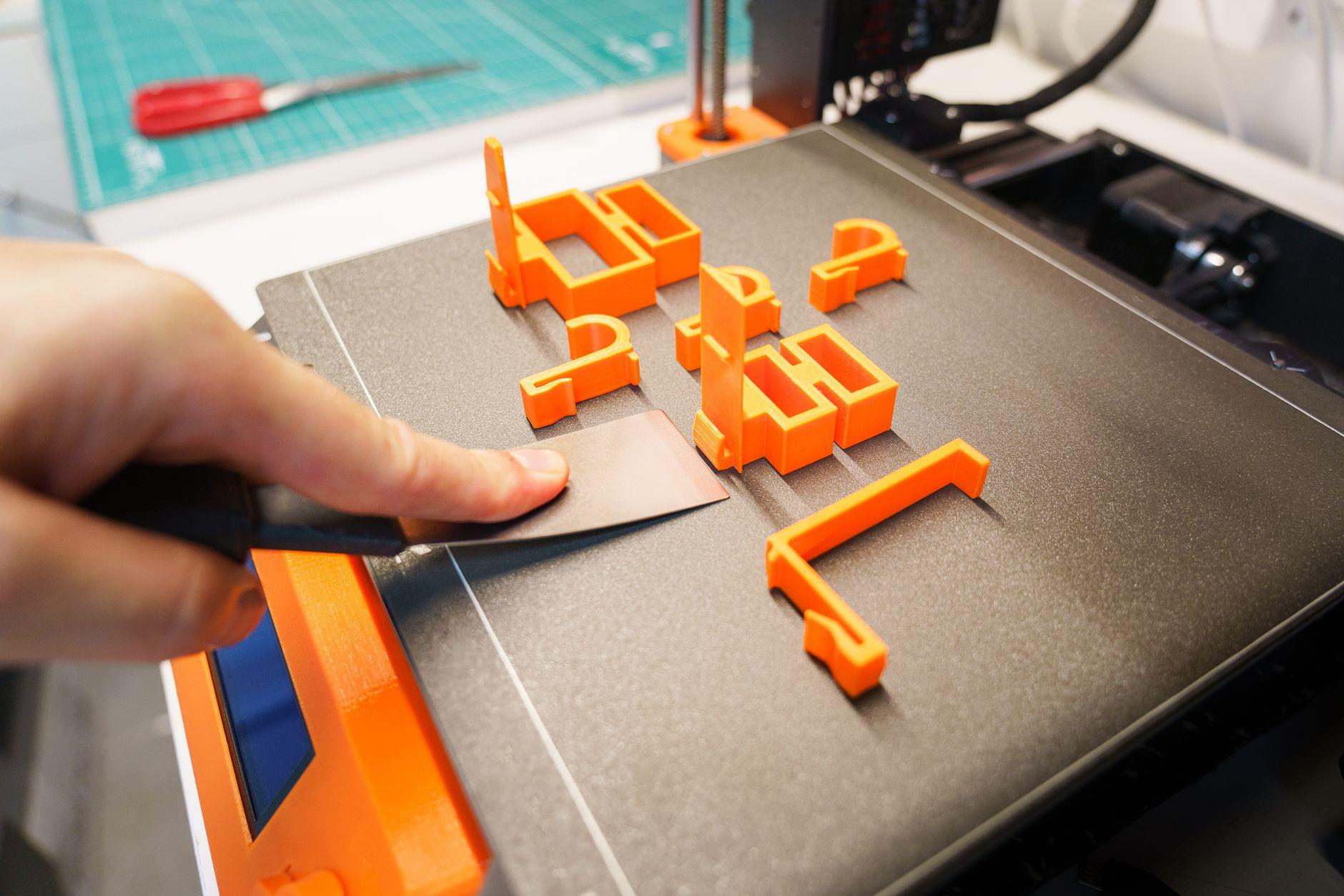
Orientation determines whether your part will be strong along the load path or weak across layer boundaries. FDM parts are inherently anisotropic: they bond layers together during extrusion, but the bond between layers is weaker than the material within a layer. Rotating your part in the build volume to align its critical stress axis along the print direction (Z-axis) will strengthen it dramatically. Surface finish also shifts with orientation, so you often need to choose between optimal strength and visual quality.
Why FDM strength depends on layer direction
When you print, the nozzle deposits plastic in thin horizontal slices, each one fused to the layer below. The plastic molecules within a single layer bond solidly to each other. The interface between layers, however, relies on the previous layer being warm enough to accept molten plastic. This bond is weaker than in-layer adhesion, creating what's called anisotropic strength: the part behaves as stronger along one axis than another.
Loads that run parallel to the layers (shear or tension along the XY plane) are resisted by the strong in-layer bonds. Loads that cross layer boundaries (tension or bending along the Z-axis) succeed only if the inter-layer bonds hold. In practice, mechanical testing confirms that layer orientation significantly impacts how much force a part can handle before failure. The weakness is not hypothetical, it is measurable and repeatable.
Assessing your load path
Before you rotate anything, identify where the stress actually lives in your part. A bracket bolted to a frame and pulled horizontally experiences tension along one axis. A hinge pin loaded in shear sees stress perpendicular to its length. A wall under deflection bends, creating tension on one side and compression on the other.
Match the strongest print direction (layers stacked perpendicular to the load vector) to your critical stress. A bracket designed to resist a horizontal pull should be printed so the layers run vertically. A shaft resisting torque should align its length along the print direction. Once you know the load path, you can rotate the part to thread the layers through that path.
Support structures and the orientation trade-off
Tilting a part to strengthen it usually increases overhang and requires more support material. The printer cannot extrude plastic into free air, so anything angled more than roughly 45 degrees without backing needs temporary scaffolding. More support means longer print time, more material waste, and extra time removing the structure by hand or chemical means.
Sometimes the strongest orientation demands extensive support. Sometimes the most economical (least support, fastest print) orientation leaves the part weak where you need strength. You must weigh the mechanical requirement against the printing cost. A non-structural prototype can live with visible layer lines and minimal support. A functional load-bearing part justifies the extra support material and labour.
Surface finish across orientations
Layer orientation also controls surface roughness. Surfaces parallel to the build platform (horizontal surfaces in the XY plane) typically print smoother because each new layer is laid down cleanly atop the previous one. Surfaces that climb the Z-axis (vertical walls) show visible stepping from the individual layer heights, creating a staircase texture.
Angled surfaces sit somewhere in between. The finer the layer height, the less pronounced this effect, but you cannot eliminate it entirely within FDM. If your part is structural and you can accept tooling marks, the strongest orientation usually wins. If the part is customer-facing or must mate with another component, you may need to prioritize finish and accept post-processing sanding or coating. The material itself also matters: PETG and ASA generally show the stepping more obviously than PLA at the same settings.
Optimizing with shell design and infill
You don't always have to choose between strength and finish. A solid wall on the exterior combined with a lower-density infill interior can deliver both. The outer shell (perimeters) prints last and can be oriented or tuned to give a smooth surface. The interior lattice or grid infill provides bulk material and can be arranged to align fibre-like reinforcement along the load path if you are using carbon-fibre composite filaments such as CF-PLA.
Infill pattern and density also interact with orientation. Rectilinear (rectangular grid) infill aligned to the load direction provides better stiffness than isotropic (omnidirectional) patterns. If your FDM printer supports it, rotating the infill pattern independently from the part orientation is another layer of optimization.
Comparing technologies: FDM, SLA, and SLS
Orientation affects all polymer 3D printing, but the severity varies. FDM suffers the most obvious anisotropy because it relies entirely on layer-to-layer fusion. SLA (stereolithography) and SLS (selective laser sintering) tend toward more isotropic (uniform) strength because the entire cross-section is cured or sintered at once, reducing the weak interlayer plane. However, all three technologies show orientation-dependent surface roughness: vertical surfaces are rougher than horizontal ones, and angled surfaces fall between the two.
For functional parts requiring the highest strength-to-weight ratio, FDM with deliberate orientation remains cost-effective. For parts where dimensional tolerance and surface finish are critical from the start, SLA offers advantages, though it adds cost and cure time. Get an instant 3D printing quote to compare how material choice and technology affect your design.
Frequently asked questions
Should I always print a part vertically to maximize strength?
No. Print vertically only if the load actually runs along the length of the part. A horizontal beam loaded downward should be printed flat (load perpendicular to the nozzle travel) so the layers resist bending. A vertical support column should be printed upright. Match the grain to the stress, not to a default rule.
How much does orientation affect surface finish?
Significantly. Horizontal surfaces (parallel to the platform) are smoother by default. Vertical surfaces show visible layer lines. Fine layer heights (0.1mm) reduce the effect but don't eliminate it. If finish matters, budget for post-processing sanding and coating.
Does material choice matter more than orientation?
Both matter. Material sets the baseline strength (choose PETG or nylon for toughness, PLA for ease of printing). Orientation then determines whether you use that strength along your load path or waste it. A strong material printed the wrong way is weaker than a moderate material printed correctly.
Can I print my part in multiple orientations to test which is strongest?
Yes, and it's a practical approach if the part is small or the load path is uncertain. Print one sample flat, one vertical, one at an angle. Load test them and repeat the winning orientation in production. This removes guesswork and is often faster than simulation for bespoke shapes.